I got a hotplate so I can make my own printed circuit boards with surface mount components using solder paste and reflow soldering.
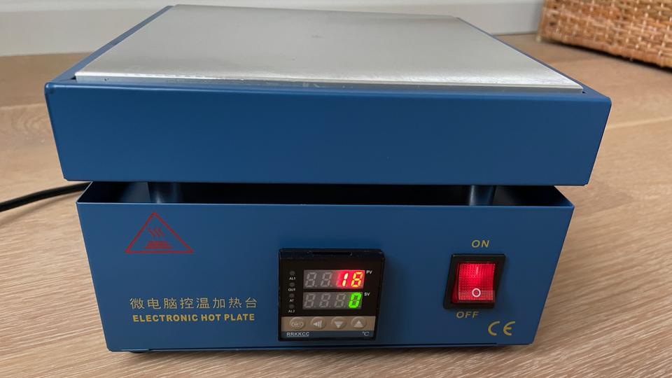
I did the first burn-in run outside on the deck. The plate gets 400°C hot, although it takes 15 minutes to get up to that temperature. I’m glad I did the burn-in outside because it did smell quite a bit. After the first run, the plate doesn’t smell at all when it gets hot.
PID tuning
The PID controller comes with some very conservative factory settings that make the hotplate quite slow at reaching the set temperature. Out of the box it takes 10 minutes to reach 300°C. You can tell the thermostat starts backing off already at 250°C to avoid overshooting. This is not great for soldering electronics—we want to minimize the time components are exposed to heat.
My controller is just labeled RRKKCC, and I couldn’t find a manual for it online. It seems to be a copy of the Japanese REX-C100 controller from RKC Instruments. I used that manual to piece together the settings for my device.
I ran a bunch of experiments with different PID settings and eventually arrived at this configuration:
| AL1 30°C |
Alarm 1. This alarm temperature is not used in the hotplate. | |
| AT 0 |
Auto-tune mode. I tried enabling this, and it made a complete mess of all the settings. Not recommended. | |
| P 10°C |
Proportional band. This controls the gain of the PID controller by setting the width of the error band where the controller output transitions from 0% to 100% heating. | |
| I 30 s |
Integral time constant. This controls the weight of the integral term in the PID controller. | |
| d 6 s |
Derivative time constant. This controls the derivative term in the PID controller. I lowered this a lot (from 60s) since this is the term that caused the controller to be so cautious about overshooting. | |
| Ar 50% |
Anti-reset windup. This is a percentage of the proportional band. I wasn’t able to figure out how this setting works. | |
| T 2s |
PWM period. The controller controls the heater from 0% to 100% using pulse width modulation. This just sets the period of the pulses. I left it at the factory default. | |
| SC 0°C |
Sensor Calibration. This number is simply added to the measurement from the k-type thermocouple sensor on the hotplate. Mine did not need any calibration. | |
| LCk 0000 |
Lock. This parameter locks various settings so they can’t be changed accidentally. I left it off. |
With these settings, the hotplate goes from room temperature to 300°C in less than six minutes.
Reflow soldering
The thermostat is measuring the temperature of the aluminum hotplate itself, but the solder paste we’re melting is going to be on a PCB on top of the hotplate. Since the thermal coupling may not be the best, I used a small PCB and a thermocouple to measure the temperature on the PCB surface. I used a bit of flux to ensure good coupling between the PCB and thermocouple:
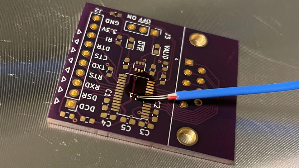
A couple of experiments showed that the hotplate is about 20% hotter than the PCB surface when measuring in °C. So to get a 250°C PCB you need a 300°C hotplate.
This is the temperature profile I get for the PCB surface when I simply set the hotplate to 300°C:
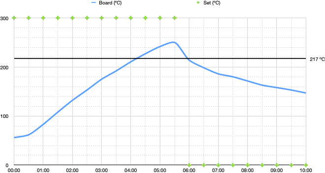
This profile meets all the requirements for reflow soldering using SAC305 lead-free solder paste:
- Preheat from 150°C to 200°C: 90 seconds.
- Time above 217°C: less than 2 minutes.
- Time from 25°C to peak temperature: less than 8 minutes.
When I tried it for real with the small purple PCB, I simply turned off the hotplate and pointed a fan at the PCB as soon as the reflow happened. It works great!